Redraw the circuit,
not your equipment
Instead of adapting your equipment to a general-purpose board, we build the board around your equipment. Communication interfaces, I/O channels, and operating voltage are engineered and populated to your order spec — from a single prototype to full production.
- Control MCU
- STM32F103 series
- Communication
- EtherCAT · RS-485 · Wireless
- Design Scope
- Circuit · Layout · Firmware
- Minimum Order
- 1 ea (prototype)
Lineup
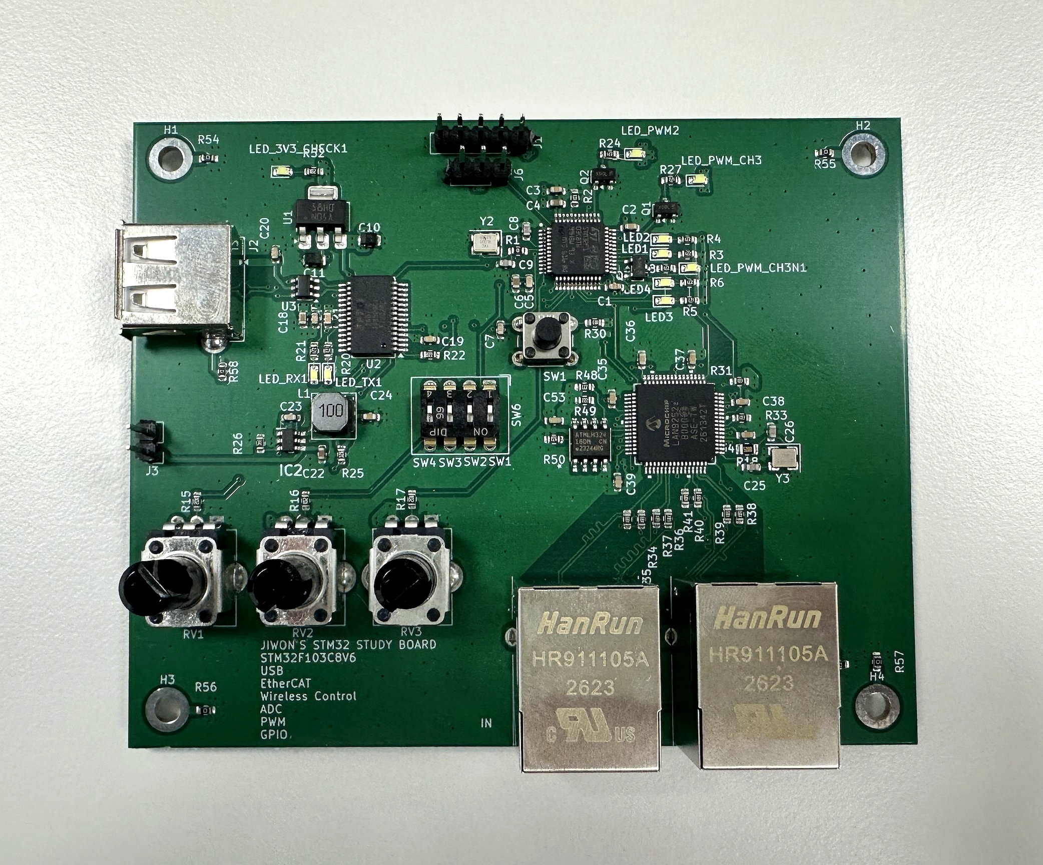
Two boards, built to order
Each board keeps a proven base design and changes only the marked sections to your order spec. Because the core stays fixed, moving from prototype to production requires far less re-validation.
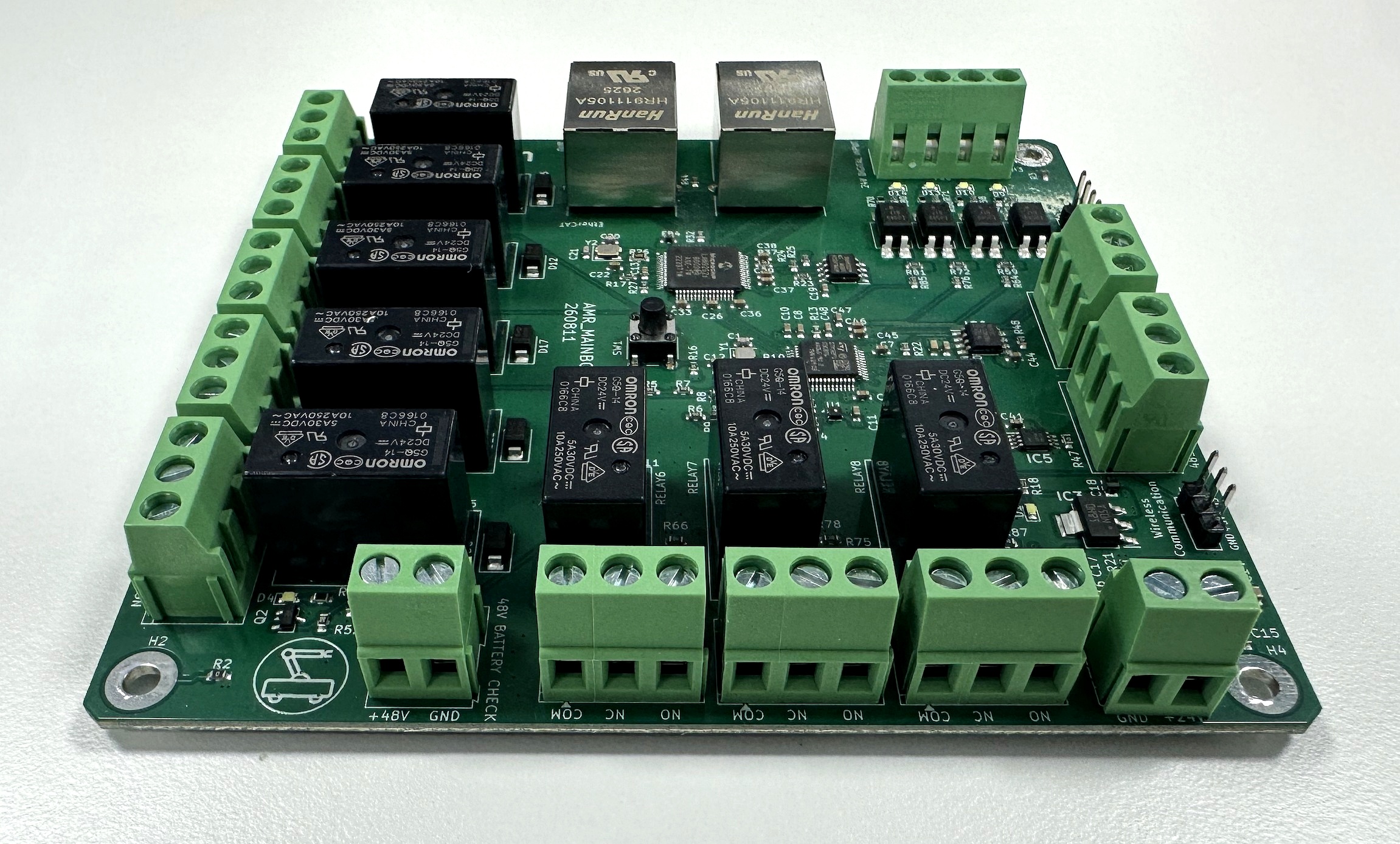
EtherCAT Control Board
An STM32F103-based control board. Communication interfaces, digital I/O channel counts and signal voltages, and relay/PWM/sensor options are all populated to your order spec.
View specs & build an order code →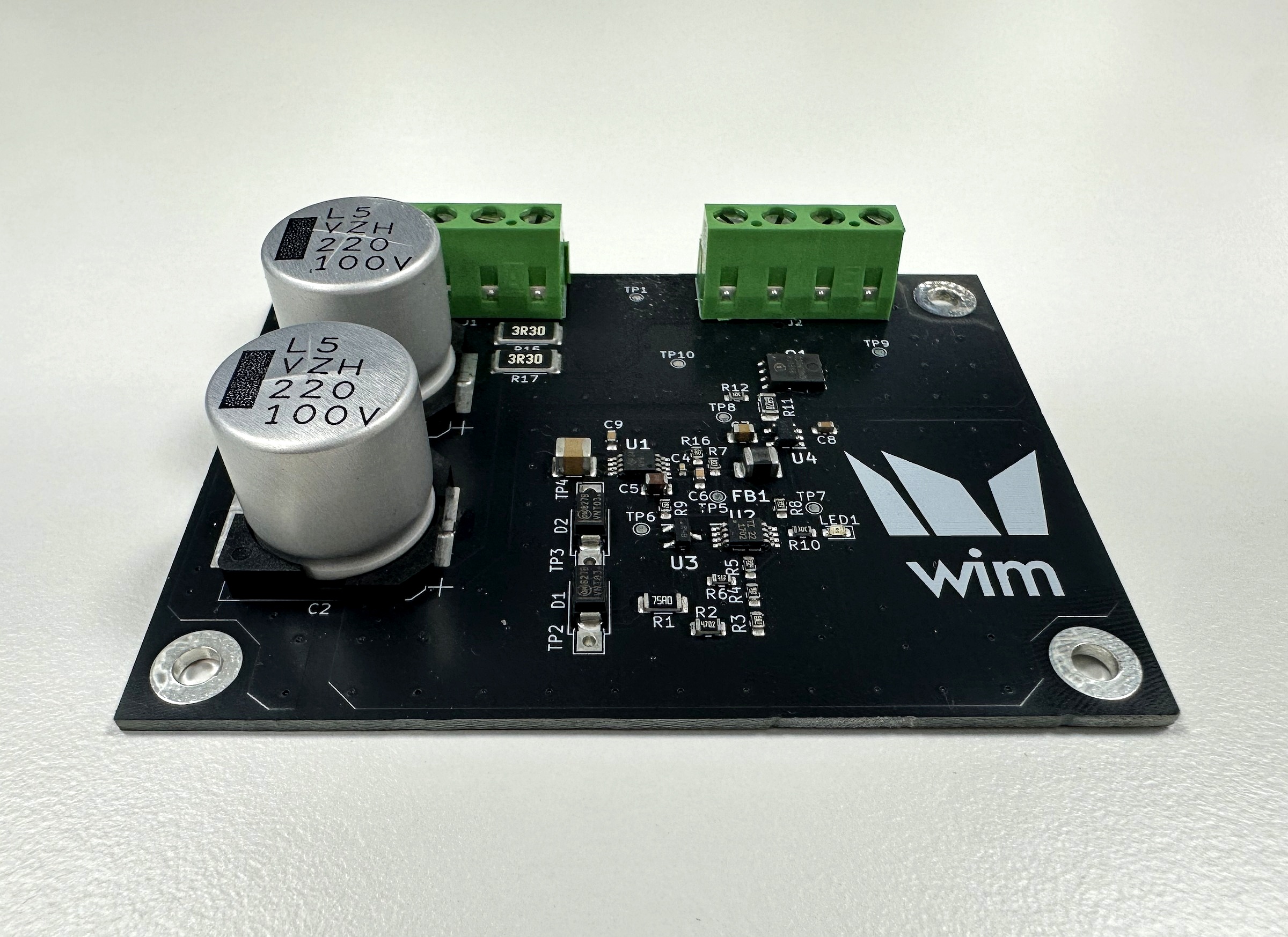
Regenerative Resistor Board
A board that dumps regenerative energy into a resistor once the DC bus voltage crosses a set threshold. Built to your specified turn-on voltage and Schmitt-trigger hysteresis band.
View voltage settings →WIM-CB100 · EtherCAT Control Board
No dead circuitry, no missing channels
The STM32F103 core and power section stay fixed, while only the communication, I/O, and sensor sections are populated to your order spec. Dropping unused connectors and transceivers cuts board area, unit cost, and power draw together.
Base Specifications
Applied uniformly regardless of order configuration.
- MCU
- STM32F103 series (LQFP48 / 64)
- Core / Clock
- ARM Cortex-M3 · 72 MHz
- Memory
- 64 KB Flash / 20 KB SRAM
- Input Power
- DC 24 V · USB 5 V
- Protection
- Reverse-polarity · TVS surge · PTC fuse
- ADC
- 12-bit · up to 10 ch
- Board
- FR-4, 4-layer · 1.6 mm
- Size
- Determined by order spec
- Mounting
- M3 mounting holes · optional DIN rail bracket
- Connectors
- Screw terminal blocks · 2.54 mm pin headers
- Debug / Flashing
- SWD header · USB DFU bootloader
- Dev Environment
- STM32CubeIDE · HAL examples provided
Customizable Items
Communication interfaces can be populated in combination, and I/O is specified by channel count and signal voltage. The code is the identifier that goes straight into the order code.
Communication Interfaces COMM
Multiple selections allowed. EtherCAT and wireless modules use significant board area, so combining them may require adjusting I/O channel counts.
Digital I/O I/O
Input signal voltage is specified at order time and populated with isolation circuitry and divider resistors matched to that voltage.
Sensors / Instrumentation SENSOR
Example firmware including value reading and calibration logic is provided.
Power Input POWER
Populating both inputs lets you flash firmware over USB while validating field operation at 24 V.
Build an Order Code
Select the specs you need and an order code is generated automatically. Attach it as-is to your quote request — we confirm the spec against this code during consultation.
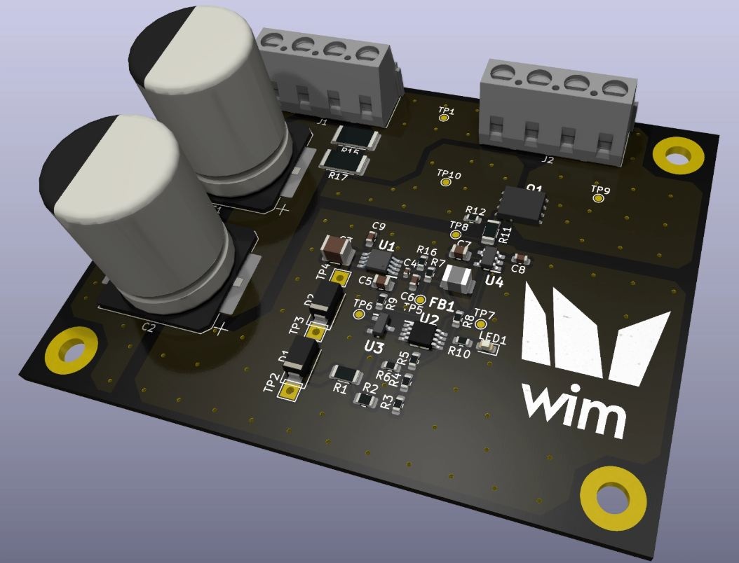
WIM-RB100 · Regenerative Resistor Board
Cross the set voltage, and regen energy goes to the resistor
A decelerating motor acts like a generator, pushing the DC bus voltage up. RB100 monitors bus voltage continuously, opens a switching element to dump energy into the regen resistor the instant the set turn-on voltage is crossed, and cuts off once voltage drops below the return voltage.
Voltage Settings
Specify the turn-on voltage and hysteresis band, and the thresholds in the graph above update accordingly. The actual settable range is finalized during consultation based on your DC bus system.
Schmitt Trigger Behavior
A single threshold causes repeated switching whenever voltage hovers near the boundary. Spacing the turn-on and turn-off voltages apart with a Schmitt trigger eliminates this chatter.
Voltage Settings Specify the turn-on voltage and hysteresis band, and the thresholds in the graph above update accordingly. The actual settable range is finalized during consultation based on your DC bus system.
Base Specifications
Circuit constants and component ratings depend on your system, so items marked TBD are finalized during consultation.
- Operation
- Bus voltage monitoring → switching discharge
- Comparator
- Schmitt trigger (hysteresis type)
- MCU
- None required — analog-only operation
- Turn-on Voltage
- Order-specified
- Return Voltage
- Turn-on voltage − hysteresis band
- Bus Stabilization
- ×2 high-capacity electrolytic capacitors
- Wiring
- 2× screw terminal blocks
- Status
- Onboard status LED
- Verification
- 10 test points (TP1–TP10)
- Board
- Size / layer count per order spec
Works
We handle design through verification in-house
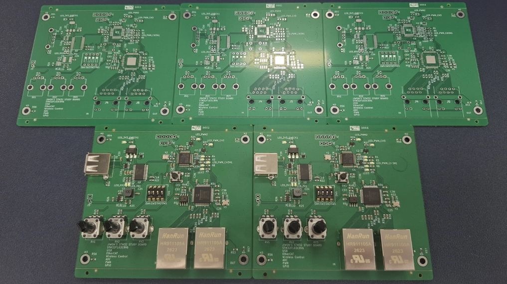
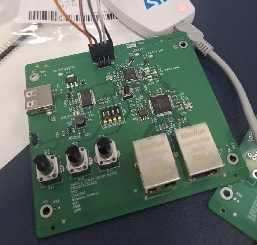
Circuit design, layout, panelization, firmware flashing, and functional verification all happen in-house — so when something goes wrong, we can trace it all the way back to the circuit.
Applications
Where it's used
AMR / Transport Robots
Connects to the host controller over EtherCAT, drives peripherals via relay, and continuously monitors 48 V battery voltage.
EtherCAT Slave I/O Nodes
Distributed I/O bridging a master controller to field sensors and actuators — daisy-chain wiring cuts down control-panel cabling.
Servo / Motor Deceleration
The regen resistor board catches the DC bus voltage spike during deceleration, preventing drive overvoltage trips.
Equipment Control / Interlocks
Isolated inputs read proximity and limit switches; relay contacts drive solenoids and indicator lamps.
Remote Telemetry
Periodically collects temperature, humidity, and voltage and sends it upstream over RS-485 Modbus or wireless.
Legacy Equipment Retrofits
Used as a gateway to add RS-485 or EtherCAT to aging equipment that only supports RS-232.
Process
Production Process
The standard timeline from inquiry to production. Varies with option configuration and quantity.
Spec Consultation
We confirm field signal types, communication environment, system voltage, and installation conditions.
1–2 daysSpec Finalization & Quote
We finalize the order code and present the circuit configuration and unit price.
2–3 daysPrototyping
Circuit design, layout, board fabrication, assembly, and firmware flashing.
2–3 weeksField Verification
We deploy to your actual equipment to verify signals and communication, and tune constants and firmware.
1–2 weeksProduction
Repeat production from the finalized drawings.
3–4 weeksInquiry
Request a Quote
Leave your requirements along with the order code you built, and our engineer will get back to you within 1 business day.